Excessive ground vibrations from foundry operations can lead to resident complaints and production risks. At a German cast iron plant, engineers deployed vibration monitoring to pinpoint machines contributing to these emissions. Using Dewesoft equipment, they identified critical sources and proposed targeted countermeasures to mitigate the impact.
Introduction
- furnaces,
- ladles,
- pouring systems,
- sand moulding machines,
- core shooters/blowers,
- cooling conveyors,
- shakeout machines,
- shot blasting machines,
- grinding stations,
- cut-off saws,
- vibratory conveyors,
- bucket elevators/pneumatic conveyors, and
- robotic handling arms.
Our client operates a foundry production facility in Germany, producing a wide range of cast iron products. Production steps include the melting, casting, cooling, cleaning, and finishing of metal parts, especially cast iron, steel, aluminum, and other alloys.
During various processing steps, we use heavy machinery with powerful engines, which produces vibrations during operation. The heavy structures and foundations of the plant are thereby also excited to vibrate often at low frequencies.
As lower frequencies in nature undergo less attenuation during propagation in the ground, they pose a risk of causing nuisance to residents in the vicinity or constraining the operation of vibration-critical technical equipment. In this case, the production facility is near a residential area, where residents have been complaining about high levels of vibrations allegedly originating from the client’s production facility.
Problem overview
In the foundry production process of casting iron parts, a critical element is the desanding of the cast parts. During casting, we pour liquid metal into a sand mould. Once the metal cools and solidifies, it emerges encased in a hard, sticky layer of sand.
The primary objective in desanding is to completely remove the sand without damaging the part, preparing it for subsequent machining operations. To achieve this, vibration motors integrated into the production line are intentionally excited to generate vibration.
Thus, shakeout machines, vibratory conveyors, and large grinding stations are often the primary vibration culprits due to their mass, unbalanced motion, and operating frequencies near ground resonance:
- Shakeout machines, which are either vibratory or rotary systems that break the sand mold and separate the casting, are a significant source of vibration emissions.
- Vibratory Conveyors that move castings or sand through the process can also contribute significantly to low-frequency vibrations.
- Grinding stations generate medium- to high-frequency vibrations due to the high-speed rotation of abrasive wheels and the impact and friction between the tool and metal castings.
For this reason, it is desirable, in the event of such problems occurring, to investigate and identify individual machines that contribute to elevated ground motion while in operation, enabling informed countermeasures to mitigate any unnecessary vibrations. Once we have pinpointed the individual machines of interest, countermeasures can include:
- Mounting individual machines elastically decoupled to avoid transmission
- Adjusting the operating frequency of individual machines to avoid resonance effects, where applicable
- Replacing entire machines with machines that emit fewer vibrations
- Replacing only critical parts of a machine with parts of a lower vibration level.
The objective of our survey was to identify the machines within the plant boundary that emit the most critical vibration.
The challenge
For economic reasons, it is essential to the client that production can continue uninterrupted, both during the day and at night, which adds to the risk of affecting or annoying nearby residents.
We use vibration velocity threshold levels specified in standards such as DIN 4150-2, the ISO 2631 series, or the British Standard BS 6472-1. These standards are used to assess the effects of vibrations on humans in buildings.
In our case, the threshold values defined in the DIN standard enable us to evaluate whether vibrations from industrial activities, such as those in a foundry, are likely to cause annoyance or discomfort to occupants. These values help determine whether operational vibrations could lead to complaints or require mitigation.
Therefore, the plant operator must ensure that the guideline values of DIN 4150-2 are not exceeded, even at nighttime, when the guideline values suggest that vibration emissions in surrounding residential buildings should be below a threshold that is hardly perceptible to humans.
DIN 4150-2: Key Vibration Guideline Values
| Time of Day | Building Use | Guideline Value | Botes |
| Day (6 AM–10 PM) | Residential | 0.2 mm/s | Slightly perceptible for most people |
| Night (10PM-6AM) | Residential | 0.1 mm/s | Barely perceptible; stricter due to sleep |
| Any time | Office/Commercial | ~0.4 mm/s | Tolerance is higher than in homes |
| Any time | Industrial/Workshop | ~0.8 mm/s or more | High tolerance due to activity level |
Before the survey, various production steps and, consequently, machines were identified as potential sources of increased vibrations.
It can sometimes be challenging to pinpoint the source of vibration emissions, especially when confronted with a complex system of individual machines operating at similar frequencies and therefore emitting superimposing waves with a highly unpredictable impact on surrounding objects.
For this reason, the client decided to conduct a multichannel survey, in which the individual machines operate independently and engineers aggregate their vibration emissions to measure and evaluate their potential to harm the nearby residential area.
The strategy
To develop a strategy for identifying the relevant machines in the plant, we consulted with the client to discuss the machines with the highest potential for vibration.
We identified eight production units on the premises as the primary sources responsible for most of the perceptible vibration emissions. We equipped the candidates and receivers with acceleration sensors.
Initially, we decided to record ground vibrations during both regular operation and plant downtime. Additionally, we ensured that individual machines operated in isolation whenever possible. By proceeding in this manner, we aimed to quantify vibration emissions from each machine, while also gaining an understanding of how the emissions of the machines interfered with one another and to what extent the impact on surrounding residential buildings might be due to the superposition of the emitted waves.
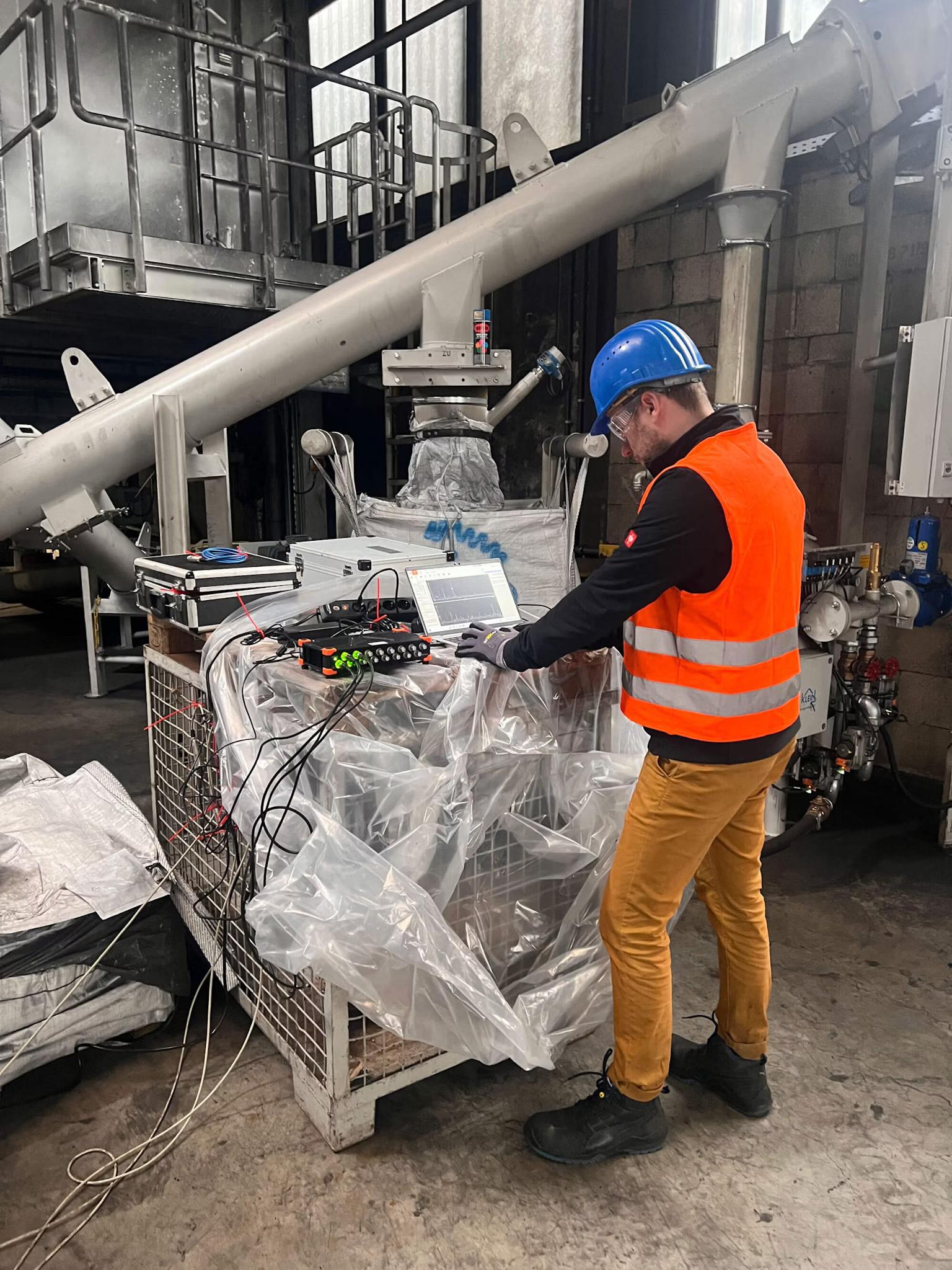
We conducted the data acquisition using a 16-channel Dewesoft SIRIUS-HD unit (Figure 1) in conjunction with industrial acceleration sensors, which have a sensitivity of 0.1 V/g.
The Result
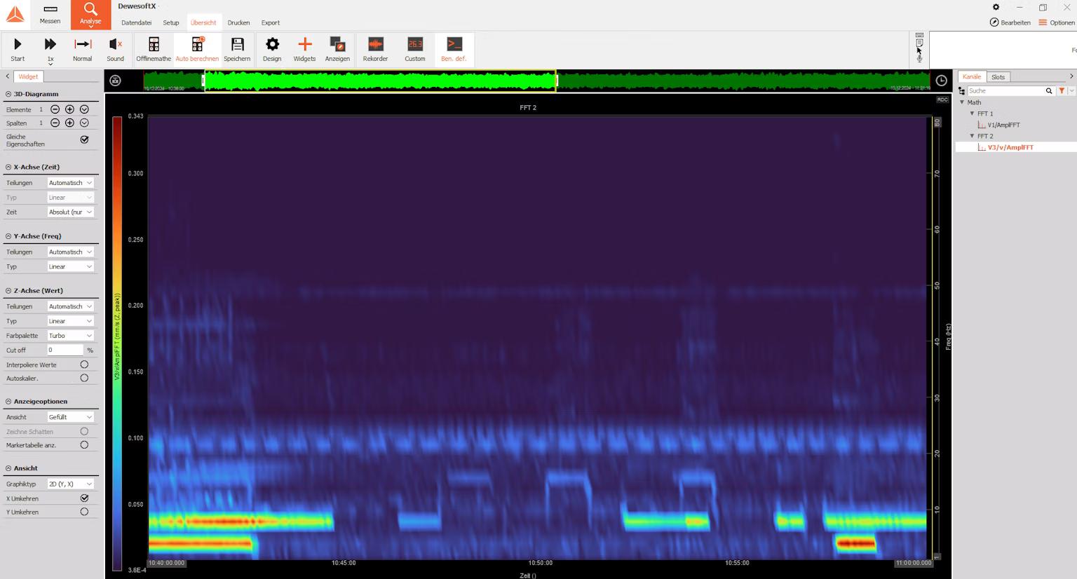
The recorded data were analyzed in the frequency domain using a Fast Fourier Transform (FFT) algorithm (Figure 2) in real-time with DewesoftX data acquisition and signal processing software. Three of the eight units exhibit elevated vibration emissions within a frequency range of 5 Hz to 9 Hz, which at times reached perceivable levels at the receiver locations.
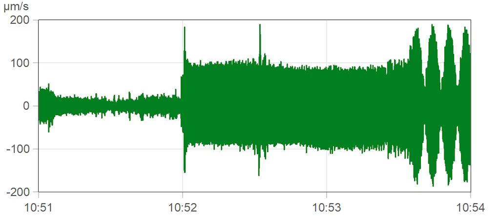
Two of the production units created vibrations at slightly different frequencies, approximately 8.72 Hz and 8.87 Hz, resulting in a modulated waveform with a period of roughly 6.5 seconds (Figure 3). Engineers refer to this effect as beating. Peak values of the modulation exceeded perception thresholds at receiver locations.
Based on these findings, individual contributors as well as the excitation mechanism were identified and pointed out to the client.
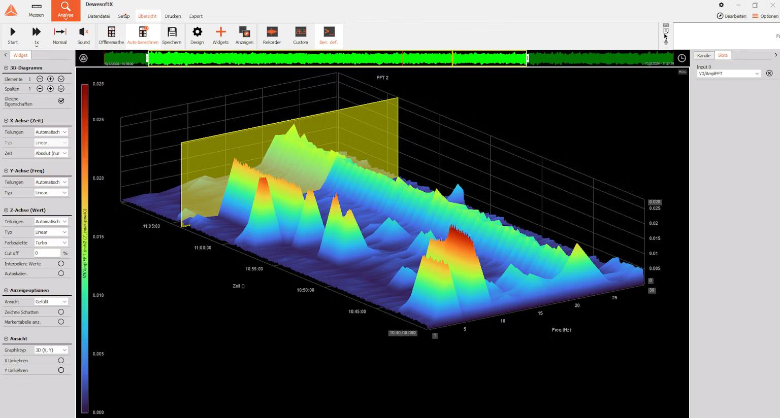
We used a three-dimensional visualization of the spectrogram (Figure 4) to demonstrate the correlations to the customer in real-time.
Conclusion
Through the investigation, it was possible to identify the primary sources of vibrations on the premises. Monitoring vibrations with Dewesoft equipment provided the data required for our analysis.
Based on the acquired results, the client organized a replacement unit for installation in the production line.
We expect that due to the difference in operating frequency and excitation forces, the change will reduce vibrations to an acceptable level. The plan is to validate this expectation with an acceptance test after retrofitting. Retrofitting and acceptance tests are pending.