General
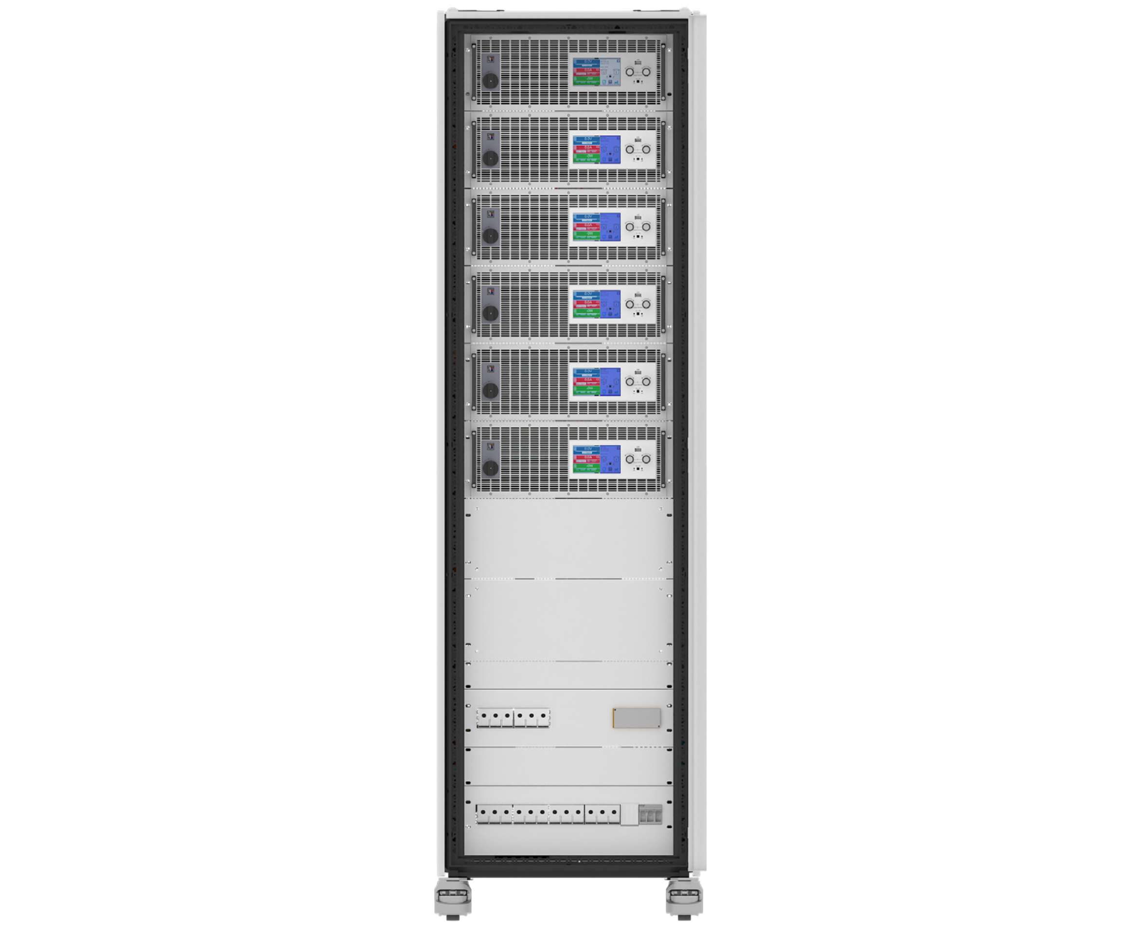
The FCTS 20920-720 provides a powerful system for high power fuel cell testing. The system works as an electronic load to discharge and stimulate fuel cells. The system is regenerative and feeds the energy back into the local grid with an efficiency up to 96.5%. The DC power of 180 kW, the DC voltage of 0 - 920 V and the DC current of 0 - 720 A is tailored for the testing of high power fuel cells. The system is equipped with a DC contactor on each pole (one in DC+ and one in DC-) to clearly separate the fuel cell from the system and to enable additional, useful functionalities. These include the active pre-charge, the reverse polarity detection and the zero current turn off functionality. In addition, the system has a temperature input to monitor the temperature of the fuel cell under test and to stop the test if the fuel cell becomes too hot. The system is installed with a high density into a 42U rack that has a width of only 600 mm and a depth of 1000 mm. The Rack has one AC input and is equipped with a 2 channel fast stop system to shut down the rack in emergency situations. The fast stop button is placed on the front of the door and the rear door is secured by door contact switches. Once the rear door opens during operation the fast stop system will be activated automatically. Also, the DC contactors are integrated into the fast stop system and disconnects the fuel cell tester from the fuel cell under test.
Active pre-charge
The FCTS offers an automated active pre-charge to avoid sparks and current peaks during contactor closing. Due to independent internal and external sense measurement, the device will pre-charge its internal capacitor without using any energy from the fuel cell under test. The FCTS will close the DC contactor once the active pre-charge is finished.
Reverse Polarity Detection
The reverse polarity detection is achieved through a second sense connection. It is a fixed installed part of the FCTS and does not change when a new test object is connected. As this part of the installation is always fix, it is not affected by a set of possible mistakes the operator might run into like • Operator might put test object and sense in reverse • Sense line might fall apart during test The FCTS offers the capability to detect such faults through the Reverse Polarity Detection!
Zero Current Turn-off
DC contactors would wear down fast if they are opened while current flows. With the “Zero Current Turn-off” function, the FCTS will always set the current to zero before opening any DC contactors. This is even possible when using the fast stop option!
Energy recovery
The energy consumed in discharge mode is fed back into the connected grid with an efficiency up to 96.5%. As the energy is not converted to heat as in other loads, the energy costs are reduced. In addition, the devices generate less heat requiring less cost intensive air conditioning.
Function generator
The system is equipped with a function generator. This allows waveforms such as sine, triangle, square or trapezoid to be simply called up and to applied either to the voltage or the current. An arbitrary generator allows voltage and current progression to be freely programmable. Test sequences for repeated tests can be saved and reloaded when needed, which saves time.
Technical drawings EA-BT 20000 Single 4U
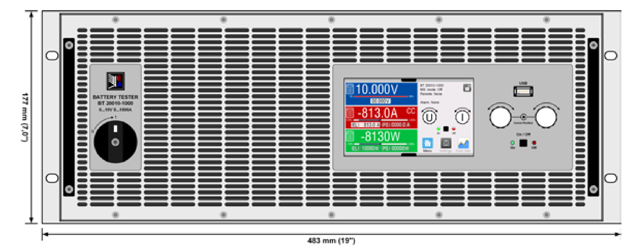
Front panel description EA-BT 20000 Single 4U
1. Power switch
2. TFT control interface, interactive operation and display
3. Rotary knob with push-button action, for settings and control
4. USB host, uses USB sticks for data logging and sequencing
5. Rotary knob with push-button action, for settings and control
6. On / Off push-button with LED status display
Rear panel description EA-BT 20000 Single 4U
1. Ethernet interfacee
2. EtherCAT ports
3. Remote sense connectors
4. Share Bus connectors to set up a system for parallel connection
5. DC output connector (copper blades)
6. AC input connector
7. Digital In/Out (16 pole connector)
8. CAN FD interface
9. USB interface
Technical drawing fuel cell test system
Technical drawing fuel cell test system
| Built-in interfaces | Software | Options |
| USB | EA Power Control | Water cooling in stainless steel |
| Ethernet (1 Gbit/s) | | Grid monitor |
| EtherCAT | | Insulation monitor |
| CAN FD | | |
| USB Host on front panel | | |
| Master-Auxiliary Bus | | |
| Share-Bus | | |
| Digital input, relay contact and temperature sensors | | |